The green and yellow earth wire is the smallest item on most bills of quantities and the one that fails inspection most often, because it is bought casually and specified loosely. An earthing conductor is not a spare core: its size is determined by the phase conductor, its identification is fixed by standard, and its continuity is a life safety function. This guide explains how earth wire sizes are derived, why the green and yellow combination is mandatory in most markets, how the wire differs from a concentric conductor or a cable sheath used as a protective conductor, and how to order and verify it. Six answers follow on sizing, colour alternatives, continuity testing and procurement.

A protective earthing conductor provides the low impedance path that lets fault current return to the source quickly enough to operate the protective device. If that path is too resistive, the device does not trip, the fault persists, and touch voltage on the enclosure rises to a dangerous level. The earth wire is therefore sized for fault current and clearing time, not for load current.
The common simplified rules serve most low voltage work. For phase conductors up to 16 mm2, the protective conductor is the same size. Between 16 and 35 mm2, a 16 mm2 protective conductor is used. Above 35 mm2, half the phase cross section is used, subject to a minimum. These rules come from the adiabatic approach, in which the conductor must survive the fault current for the time the protective device takes to operate, and they are accepted in IEC-based practice and repeated in most national guides.
The wire itself is usually a single core, PVC insulated, class 1 or class 2 copper conductor, in the fixed wiring sizes from 1.5 mm2 upward. In installations where mechanical damage is possible, it may be run in conduit or be part of a multi-core cable. In cable constructions, the protective conductor is either an integral core, sized by the same rule, or a concentric layer of copper wires, which is why certain European cable types carry a concentric conductor rather than a separate earth core.
| Phase conductor S | Protective conductor | Typical use |
|---|---|---|
| Up to 16 mm2 | S | Final circuits, distribution boards |
| 16 to 35 mm2 | 16 mm2 | Sub-mains |
| Above 35 mm2 | S/2 | Main distribution |
| Any | Minimum per standard | Mechanical strength floor |
The green and yellow combination is reserved exclusively for protective conductors in the IEC system, and that exclusivity is the point. A technician opening a junction box must be able to identify the protective conductor instantly and with certainty. Reusing the combination for a switched live or a signal core destroys that certainty, and the mistake is repeated across an installation once a precedent is set.
North American practice uses a bare conductor, a green conductor, or green with a yellow stripe, and the choice is governed by the applicable code and the wiring method. What matters for a supplier is that the identification stated on the order matches the destination market; shipping IEC green-yellow into a project that expects a bare conductor creates a rejection even though the copper is correct.
Continuity is the second issue. An earth wire that is correctly sized but poorly terminated provides no protection. Terminals must be suitable for the conductor class, the connection must be mechanically secure, and the protective conductor must not rely on a screw that also carries mechanical load. In cable trays and metal conduit systems, the tray or conduit is not a substitute for the protective conductor unless the standard explicitly permits it and the joints are bonded.
The third issue is mixed metal work. Where dissimilar metals meet at a termination, corrosion can raise resistance over time. Aluminium conductors require appropriate connectors and, in damp locations, suitable compound. A copper earth wire bolted to a galvanised steel frame without a proper terminal will pass a commissioning test and fail years later.
Finally, the cross section rules are minimums, not targets. Long earth runs add impedance, and where the total loop impedance is close to the limit for the protective device, a larger protective conductor or a supplementary bonding conductor may be required. Products such as the Temperature Rating -20C To 70C Multi Core Sheathed Steel Wire Armored PVC Insulated Cables For Underground Ins and the CYKY 5x10mm2 Oxygen-Free Copper PVC Insulated Underground Distribution Cable 0.6/1kV Outdoor show how integral and concentric protective conductors are built into finished cables.
State the phase conductor size, the protective conductor size you require, the identification, the conductor class and the standard, then add the packing. A line that reads green-yellow PVC insulated earth wire, 1x16 mm2, class 2 stranded copper, 450/750 V, IEC 60227, on 100 metre coils is unambiguous and cannot be substituted by a 10 mm2 product sold as the nearest size.
Do not accept a bare statement of the cross section without the strand count. A 16 mm2 conductor built from fewer, thicker strands meets the resistance requirement but is stiffer and harder to terminate in a small earth bar. Where flexible panel wiring is involved, specify a fine stranded class and use ferrules.
Check the colour on delivery, not only on the label. Green-yellow insulation should show a continuous and clearly defined two-colour pattern rather than a thin stripe on green or a smeared print. A compound that gives a weak colour distinction is a legitimate quality complaint, because the identification requirement is part of the standard, not decoration.
Verify the conductor by measuring resistance on a sample length, or by measuring strand diameter and count and comparing against the class table. Record the result against the batch. Where the earth wire goes into a project with a documented inspection regime, keep the test sheet and the retained sample together, so that a query months later can be answered from the file rather than from memory.
Plan continuity testing into the handover. A simple end to end resistance measurement on each protective conductor, recorded on a drawing, demonstrates compliance and protects the installer. Faults are almost always at joints and terminations rather than in the wire, and the test finds them before the client does. The protective conductor is also the item most often omitted from variation orders, so keep a stock allowance on site rather than discovering a shortfall during commissioning.
Where the protective conductor is inside a multi-core cable, its size follows the same rule as a separate wire, but its construction differs. It may be a reduced core, a concentric layer of copper wires over the cores, or a copper tape in contact with a drain wire. Each arrangement terminates differently, and each has a different behaviour under fault current.
A reduced core is the simplest and terminates like any other core. A concentric layer gives a low impedance path and is mechanically protected, but it needs a proper gland or clamp to make the connection, and a careless termination leaves most of the copper unused. A tape screen is a screening solution that can carry fault current only if it is correctly bonded at both ends, and the cross section is often smaller than a dedicated conductor would be.
Earth continuity is verified by measurement, not by inspection. A low resistance ohmmeter applied between the earth bar and the far end of each protective conductor gives a number that can be recorded and compared with the design value. Doing this for every circuit takes time, but it is the only way to find a conductor that is connected but broken inside a joint.
Documentation completes the job. A handover pack that includes the earth continuity results, the earth loop impedance readings and the drawings showing the protective conductor routes protects the installer and gives the client a baseline for future maintenance. When an alteration is made years later, that baseline is what allows the change to be verified rather than guessed.
Extending an existing installation is where earthing mistakes concentrate, because the new work must match a system designed years earlier, often without complete records. The protective conductor size must be checked against the new phase conductor, and the connection point must be verified as a genuine earth path rather than an assumption.
Two checks resolve most cases. First, measure the earth loop impedance at the extremity of the new circuit and compare with the value required for the protective device. Second, verify continuity back to the main earthing terminal by resistance measurement, not by looking at the drawing. Where the results are marginal, a larger protective conductor or additional bonding is cheaper than redesigning the protection.
Materials matter in retrofit work. Old installations may have aluminium or tinned conductors, and mixing metals at a new joint requires appropriate connectors. A joint that looks sound but corrodes will fail a periodic inspection, and the cost of returning to fix it exceeds the cost of doing it properly once.
The earthing rules are short and they are worth repeating at every project meeting, because they are the items most often skipped under schedule pressure. Size the protective conductor from the phase conductor, keep the identification exclusive, terminate with suitable hardware, and measure continuity rather than assuming it. Four rules, four failure modes avoided.
On a large project, a short briefing for the installation team on these five points costs an hour and prevents the rework that otherwise consumes days at handover, when the pressure to finish is greatest and the cost of correction is highest.
For phase conductors up to 16 mm2 use the same size; 16 to 35 mm2 use 16 mm2; above 35 mm2 use half the phase size, subject to the minimum in the standard.
In IEC markets the combination is reserved for protective conductors and the two-colour identification is expected. Some markets accept green alone; confirm the project requirement.
Yes where the standard and the cable construction provide it, and where the terminations maintain continuity. It must be identified and connected as a protective conductor.
Not necessarily. Class 3 or fine stranded conductors are acceptable where the standard permits, and they are easier to terminate in small terminals.
Only where the standard permits it and joints are bonded to maintain continuity. A separate conductor is the safer default.
Small sizes on 100 metre coils in multiple colours, larger sizes on reels. State the coil length so the site does not run short.
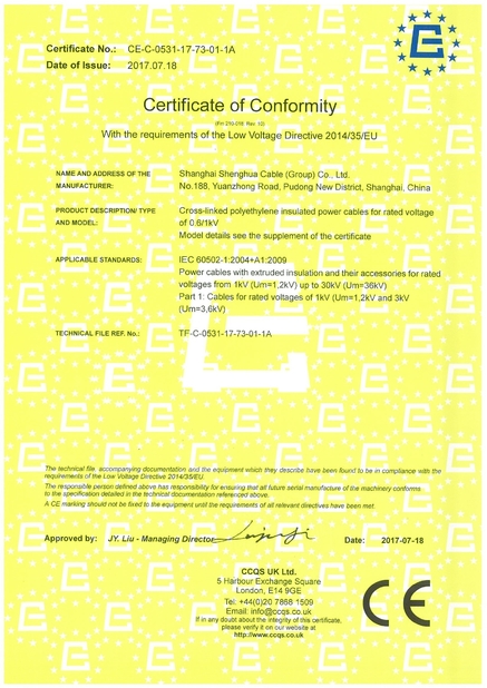
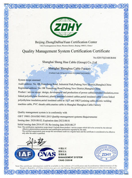
The earth wire is a safety component with a defined size, a reserved identification and a continuity requirement, and it deserves the same specification discipline as the phase conductors. Size it by the rule, state the colour, class and standard on the order, verify the colour and the conductor on delivery, and record continuity at handover. Shanghai Shenghua Cable Group supplies green-yellow PVC insulated earth wire from 1.5 mm2 upward, in class 1, 2 and fine stranded constructions, on coils or reels, with the resistance data and standard reference quoted per item. Send your earthing schedule through our contact page and we will confirm sizes and packing. Related items include the N2XRY 4x35mm2 Oxygen-Free Copper PVC Insulated Wire Armoured Power Cable 0.6/1kV Underground, the Multi Core 300V Sheathed Steel Wire Armored PVC Insulated Cables Coiled For Underground Use, the 21/35kV XLPE Power Cable - Earthquake & Corrosion Resistant, the NYY 4x25mm2 Oxygen-Free Copper PVC Insulated Low Voltage Power Cable 0.6/1kV Underground, the 0.6/1KV Underground Armored PVC Insulated Cables -20C To 70C For Underground Power Distribution Solutions and the Shenghua Group Power Cable NYY NYCY Electrical Fire Resistant Cable For Buidings / House Wiring.